


Why Ripple Matters for the Precision and Reliability of Programmable DC Power Supplies?

Should you have studied the data sheet and specifications of ActionPower’s CORTEX DC Bidirectional Programmable Power Supply you would have noticed the following parameters that stand for its accuracy and precision, taking CORTEX model CD15-040B for example:
| Voltage Output Parameter | Specification |
|---|---|
| Programming Accuracy | ±0.002% F.S. |
| Display Accuracy | ±0.002% F.S. |
| Line Regulation (CV) | ±0.01% F.S. |
| Load Regulation (CV) | ±0.01% F.S. (0–100% load) |
| Programming Resolution | ±1 mV |
| Ripple and Noise (p-p, CV) | <300 mVpp |
In the worst case, supposing we first consider only the steady-state DC terms, the average voltage deviation is about ±10.6 mV, corresponding to approximately 39.989–40.011 V. When the specified ripple and noise (< 300 mVpp) are then superimposed on this stable DC level, the instantaneous output can swing by roughly ±150 mV around the average value. This shows that while the DC accuracy is at the millivolt level, the ripple dominates the instantaneous voltage window, leading to a conservative overall range of about 39.84–40.16 V.
What is implied by this example is that, while usually neglected and not attached with much attention, the specification of ripple can be a deterministic factor for how precise and accurate a programmable DC power supply is. Further, when setting up a testing bench, the DC power source’s accuracy will then affect the system’s overall testing accuracy. Ripple, among those parameters that deal with precision, is what will be covered in this article by which we will explain why this is the key specification that determines a DC programmable power supply’s performance. For more product information, you may search through our power supply wizard instead, where you may locate the right model option for your testing.
What is Ripple of DC Power Supplies?
Ripple refers to the remnant AC component with a DC voltage or current output which is featured by a cyclical pattern appearing to be with slight, upward and downward fluctuations over the presumably ideal DC level of the output. One fact that should be addressed with attention is that ripple is a different unwanted component compared to noise. While ripple follows a periodical pattern, noise occurs randomly along a waveform and is rather sporadic and unpredictable. The below picture visualizes the differences between ripple and noise when on a waveform.
 Fig 1. Examples of Ripple and Noise
Ripple happens typically with either switching power supplies or linear power supplies though each of them operates with different mechanisms due to which ripples are produced. Respectively,
- With linear power supply, ripple caused due to the existence of transformer and rectifier comes with relatively lower frequency ranging typically around 100/120 Hz and low peak-to-peak value of . They are easy to filter with the case of linear power supply.
- Switching power supplies reply on the operation of switching components which results in high-frequency ripples – with its cycle often tends to be 20 times more high than that of linear power supplies.
Why Does Ripple Matter for Programmable DC Power Supplies?
A programmable DC power supply implemented for a laboratory test bench draws firstly supply from local utility of AC and rectifies it into DC power when it is connected with the EUT. However, it is inevitably unperfect because it is practically impossible to eliminate completely the remnant AC component after rectification, rather, to minimize it as technically efficient as possible. A ripple specification thus is a key parameter to define how precise and accurate a programmable DC power supply is.
 Fig 2. Adverse Effects of Ripple on EUT during Testing Application
Primary adverse effects on the EUT due to a programmable DC power supply with high ripple may include:
Behaviors contaminant to EUT during testing
A DC source with high ripple is in nature a disturbance source rather than a stable reference of pure DC. The results will be increased measurement uncertainty, especially at low current levels, while on the side of the EUT which comes with correction circuits on its own such as DC/DC, BMS, MPPT, inverter controllers it means contamination to its behaviour and functioning during the testing due to its continuous internal corrections.
Additional Thermal Generation
Some EUTs like DC/DC converters, on-board chargers, servers, PCS, and inverters come with an integrated filtering stages among their circuits. The ripple contaminated waveform fed from the non-ideal DC source impose additional stress on these circuits, causing extra energy dissipation for filtering the noise. The worst case can be the triggering of over-temperature protection during the testing, beyond the lower measured efficiency. The ripple, in case, turns the testing scenario into “testing the power supply rather than the device”, leading to overly pessimistic results.
Compliance and Standards Impact
Standards and regulations such as IEEE 1547 and IEC 61000 series suggest a series of requirements over the power source to be used for testing application. A non-ideal power source with high ripple violates the assumption and prerequisite of the testing that the source is ideal and clear, then further delivers misleading results and even the certification may fail.
Explanations with Full-Bridge Rectification: How Do Ripple Come into Being?
To explain how ripple comes into being we take the full-wave bridge rectifier’s operation and functioning as example for your better understanding.
 Fig 3. Current Flow in a Bridge Rectifier during the Positive and Negative Half Cycle – Credit: Analog Devices
In a basic AC–DC conversion, DC ripple originates from the mismatch between discrete capacitor charging–discharging and continuous load consumption. For a single-phase full-bridge rectifier with a filter capacitor , the input is:
and the rectified waveform becomes as below, which stands for that the circuit transposes the negative half cycle into the positive:
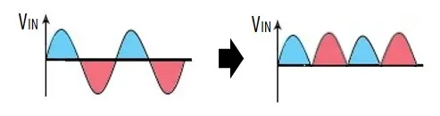 Fig 4. Waveform before and after Rectification
To smooth this pulsating voltage, a capacitor is placed across the output. Near each peak, the capacitor charges quickly; when the rectified voltage falls, the diodes turn off and the capacitor discharges to the load. Assuming an approximately constant load current , the voltage drop during discharge is:
where for a full-bridge rectifier. This produces a sawtooth-like ripple, whose peak-to-valley value defines the ripple voltage.
 Fig 5. Resulting Waveform after Rectification with Ripple
In frequency terms, this process adds AC components at and its harmonics on top of the DC level. Ripple therefore reflects a periodic energy imbalance between the capacitor and the load: higher load current, smaller capacitance, or larger internal impedance all increase ripple.
Modern switching supplies use high-frequency conversion and multi-stage filtering to reduce ripple, but residual ripple is unavoidable due to finite control bandwidth and parasitics. Thus, DC ripple is an inherent result of the rectification–storage–discharge process and a key indicator of power supply quality.
How to Minimize the Ripple with Programmable DC Power Supply?
Minimizing output ripple is a fundamental design objective of high-performance programmable DC power supplies, especially for precision testing, power electronics validation, and EMC-sensitive applications. At ActionPower, ripple suppression is achieved through a combination of proprietary digital control architecture, high-resolution sensing, and advanced closed-loop algorithms rather than relying solely on passive filtering.
At the hardware level, ActionPower uses a dedicated high-frequency ripple detection circuit on the DC output path to monitor ripple from to
in real time. This enables precise observation of both low-frequency drift and high-frequency switching noise.
On the control side, a specifically developed DSP/FPGA-based digital controller performs fast closed-loop regulation and actively suppresses residual ripple by dynamically adjusting modulation in real time. In addition, advanced signal-processing techniques improve the effective number of bits (ENOB) of the ADC, reducing quantization noise and enhancing detection of small ripple components.
Combined with multi-stage output filtering and high-frequency conversion, this integrated sensing-and-control approach delivers ultra-low ripple performancewhile preserving fast transient response, ensuring clean and stable DC output for precision testing and high-quality industrial applications.
Discover ActionPower’s Low-Ripple Programmable DC Power Supplies
ActionPower‘s programmable DC power supplies often combines noise and ripples into a single specification as you will find when reviewing through our product pages, now that the DC output is a combination of DC source, ripple, switching noises, control residual and EMI coupling where the noise are unwanted interference that is difficult to measure and differentiate. Despite these facts, ActionPower’s programmable DC power supplies are with ultra love ripple.
Whether you are conducting precision laboratory measurements, EMC testing, power electronics validation, or high-reliability industrial applications, our solutions help you minimize measurement uncertainty, improve repeatability, and ensure that your results truly reflect the behaviour of your device – not the limitations of your power source. Explore how ActionPower’s low-ripple technology can elevate your testing performance and support your most demanding applications.


 목록으로
목록으로  댓글쓰기
댓글쓰기  0
0 


총 0건의 댓글이 있어요
댓글 0